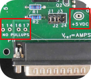
Figure 1 – HobbyCNC PRO Output Pins
To add spindle control, the HobbyCNC PRO board (Not the EZ) provides easy solder-pad access to four generic ‘output’ pins – Pins 1, 14, 16 & 17 (Figure 1). These pins are typically configured in your CAM software to control different functions – e.g. a spindle or a coolant pump.
These 4 pads are ‘courtesy’ pins that connect directly to the D connector. There is nothing else connected to these pins (as indicated by “NO PULLUPS”). So, technically, we (HobbyCNC) don’t support any type of control – we only pass these wires through from the 25pin D connector for these 4 signals. If your control software sends the proper signals through these pins, then you are in great shape.
Connecting to a spindle or pump
For simple on/off control of a pump or spindle, some type of relay (or equivalent) is required to allow the low voltage/low current of the computer to drive a high voltage/high current output. A spindle can easily draw 10 amps at 120 Volts AC. Some examples of how to do this are provided here:
Does your board support VFD or PWM?
Do you support VFD (Variable Frequency Drive), PWM (Pulse Width Modulation) or PDM (pulse density modulation)?
As stated above, the HobbyCNC board does not ‘support’ any type of output control (except the stepper motors). On the HobbyCNC PRO board, four pins are provided that will output whatever signal(s) are generated by your software.
Some videos suggested by our users
LinuxCNC Huanyang VFD, home switch, and joypad configuration
Homemade DIY CNC, How to control a Huanyang VFD inverter with Linux CNC
