
I decided to offer assembled HobbyCNC PRO boards. As it turns out, not all of my customers are handy with a soldering iron, or they want their results quicker! So I build the boards, by hand, 10 at a time. Not a big deal. Testing them, however, is a big deal. I test these boards under full power – four motors at 3 amps each. That’s 24 screw terminals, plus 2 for power and 2 for the fan.
So I decided to build a ‘board of nails’ tester using my 3D printer to make the framework and my CNC router to make the PC board.
I purchased the spring test (pogo) pins from a Chinese supplier on eBay, though I found this electronic components database afterwards that I may make use of next time. These are small (33mm x 1.36mm dia) spring-loaded pins with an aggressive head on them, designed to make good electrical contact on uneven surfaces.
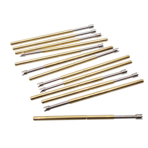
Fig 1 – Bunch of Pogo Pins.
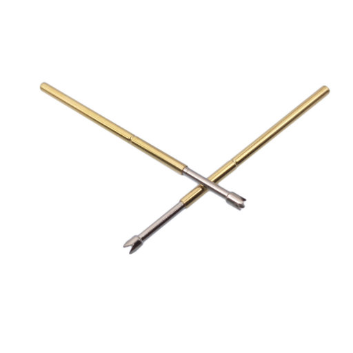
Fig 2 – Fewer Pogo Pins.
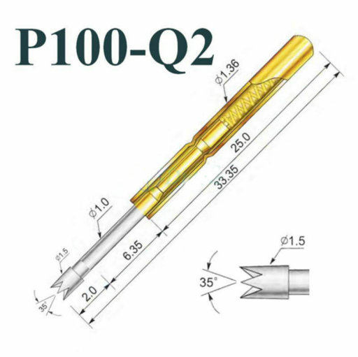
Fig 3 – Pogo Pin dimensions.
So I decided to build a ‘board of nails’ tester using my 3D printer to make the framework and my CNC router to make the PC board.

Fig 4 – 3D printed pogo board support frame
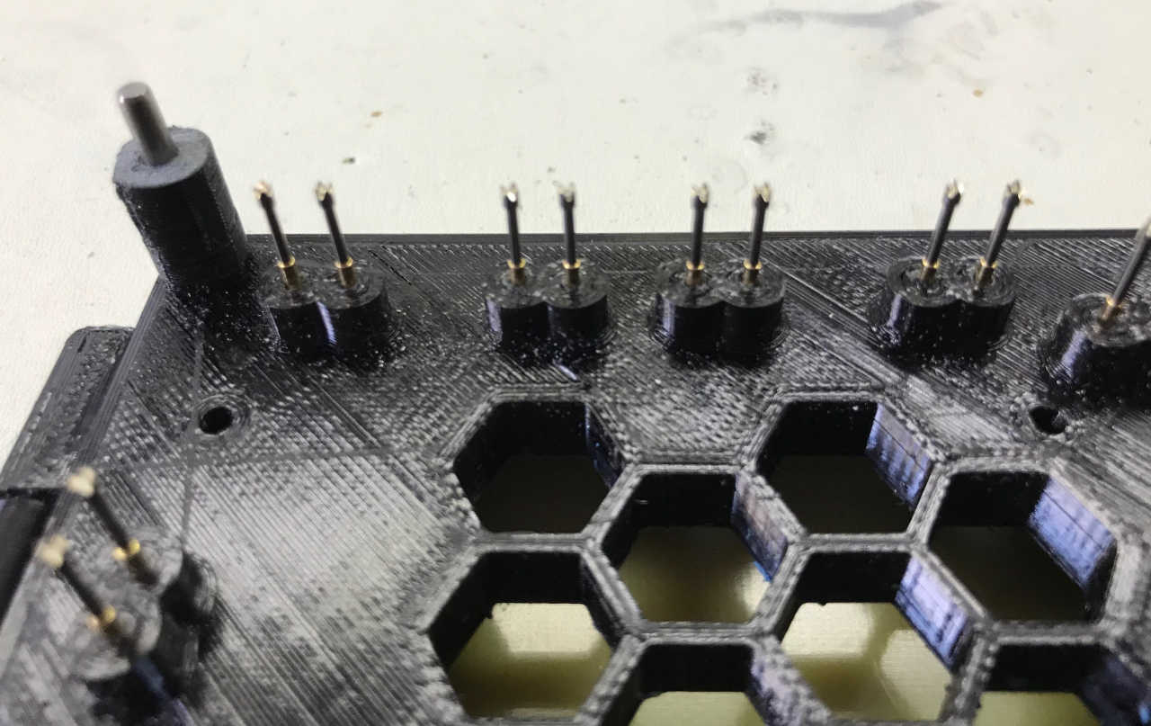
Fig 5 – Pogo board details showing pogo pin supports and alignment/mounting pin for board-under-test.
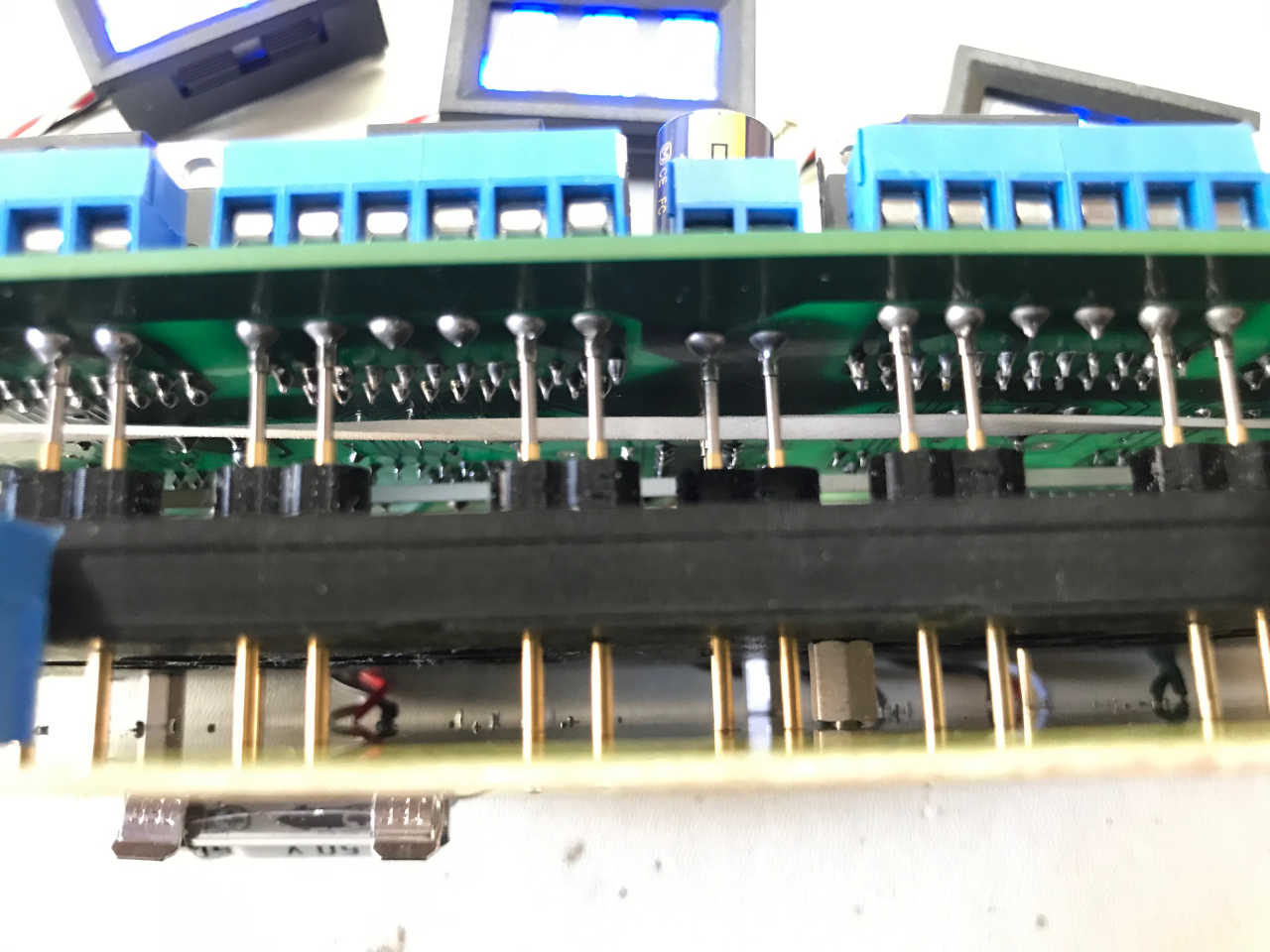
Fig 6 – Underside of Board-Under-Test showing Pogo Pins resting on the motor driver connectors and power connector.
I added three inexpensive voltmeter modules to give me real-time readings as the board is being tested.
The PC board to test slides down on the four corner alignment pins and the side clips come over to hold the board. The volume of pogo pins is large enough to bow the board under test, so I need to install the heatsink before testing to ensure the board being tested lies flat.
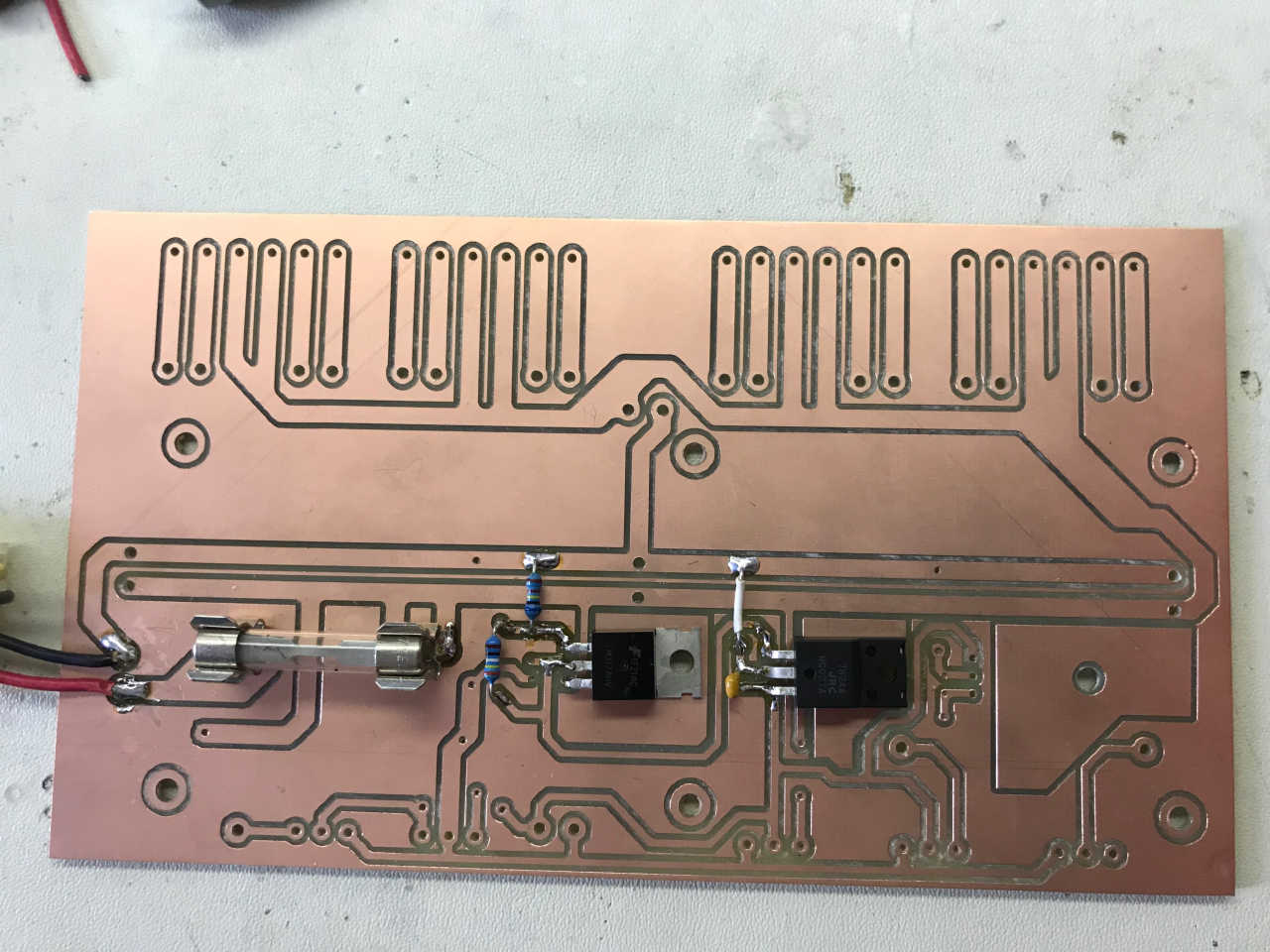
Fig 7 – PC Board assembly started. All parts are mounted on the ‘wrong’ side in case service is needed.
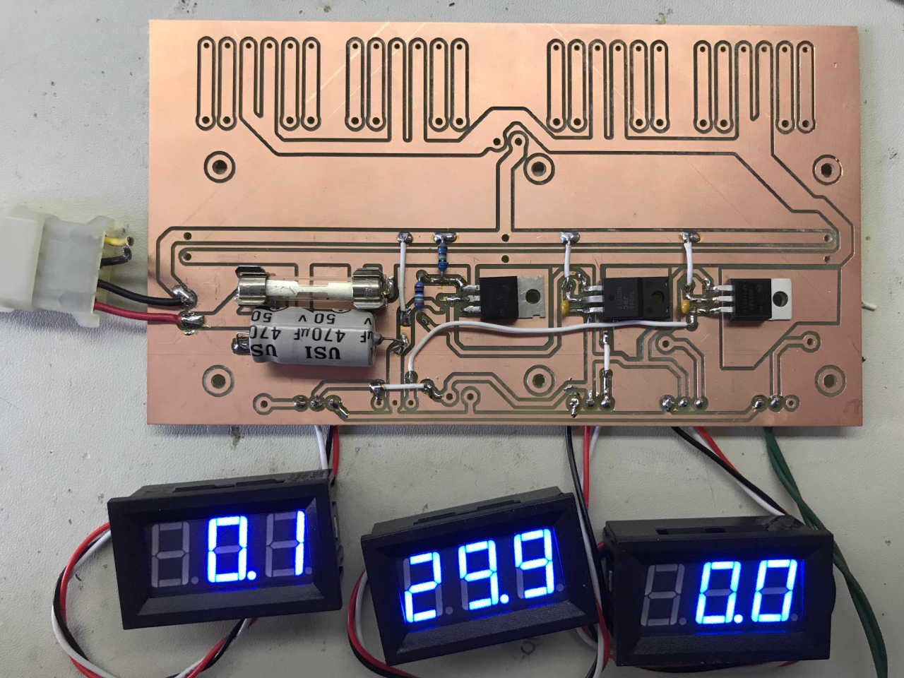
Fig 8 – Assembly is complete. Jumpers necessary because this is a single-sided PCB.
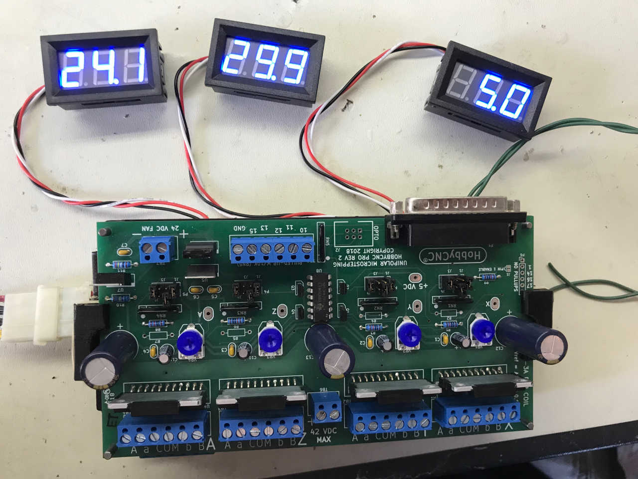
Fig 9 – All assembled and Board-Under-Test is in place. Volt meters read raw voltage in (29.9V), fan voltage (24.1V) and logic voltage (5.0V)
I hooked everything up to my test jig (power supply and motors). I run each board through a series of tests at full current (3 Amps). To make sure no steps are missed, I made little pointers. These pointers need to finish pointing the same direction (Left two motors are paired to one axis and the right two motors to the other axis).
After successful testing, the heatsink is removed, the pots are dialed-back to about the middle and the board is packaged for shipment.
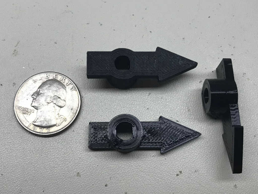
Fig 10 – small, 3D printed arrows help me ensure there are no skipped steps.
Video – Short video of part of a HobbyCNC PRO test sequence.
how can I get one these setups
Raymond, Which setup in particular?
A HobbyCNC board, The test board, a bed-of-nails tester?
Thanks, BrianV