Making sure your stepper motor wiring is robust and secure is critical. Most (all?) stepper motor driver instructions include the warning “do not connect/disconnect motors while power is applied”. Curious why?
A brief-yet-incomplete intro to stepper motors is appropriate. Stepper motors contain several windings. These windings are very large inductors. By their nature, inductors a) resist changes in current flowing through them and b) store energy in the magnetic field they create.
Steppers are often rated at a very low voltage and fairly high current – like 3 Volts and 3 Amps per winding. Yet we suggest a very large power supply, at 36 Volts (or more depending on the driver). My board (and most others) energize a winding by slamming (a technical term) the voltage to the winding and monitoring the current flow. When the current hits the max setting, the board backs-off the voltage, in my case by using a chopper technique – often you can hear the motors ‘whine’ at the chopper frequency.
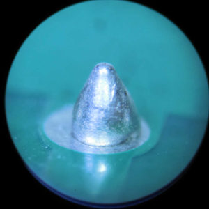
So what happens when you mess with the wires while the motor is powered-up? Here’s one example. Take a close look at the solder joint in Figure 1. This is the common for the a-A winding at the terminal strip for the x-axis. The solder is hanging onto the pin, but not making good contact to the PC board trace. It worked for an hour-or-two. At some point, this connection opened-up.
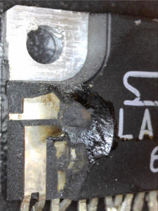
Remember all that power stored in the winding? It’s going somewhere. Since it couldn’t go through the common pin, it had to go through the driver chip – causing enough heat to blast-off a chunk of the driver IC.
For the record, this is NOT covered by warranty.
Pro Tip: Make double-sure your power supply is at zero volts before you mess with any stepper motor wiring!

Figure 1. Bad solder joint (magnified 40x)

Figure 2. Blown driver chip

So can’t you add some kind of shunt to protect the circuits?
Thanks for the article.
Excellent question and right-on-the-mark! There is indeed a shunt circuit built into the driver chip. However, the bad solder joint effectively removed the shunt from the circuit.
That bad solder joint was where the stepper connects to the PC board. So, this example simulates disconnecting the stepper while power is applied – the whole issue revolves around exactly what you suggest – disconnecting wiring can effectively remove any shunting of that excess power.
Make sure the wire connections to your stepper motors are solid, as this has caused 2 of my drivers to fail.
This will then stop the power output from the power supply to shut down.
In other words this was seen as a disconnect during power on.
Good input. Connections can loosen-up over time. An occasional re-torque makes sense.
It doesn’t matter how/where the connection opens-up: they’re all bad!
I have read in numerous forums not to do this and now I know why must have mad a pop