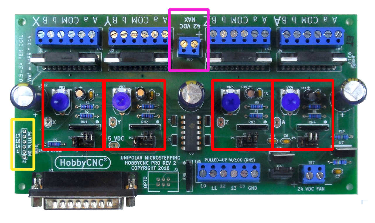
I’ve made a few changes to the popular HobbyCNC PRO board. Most of the changes are cosmetic or functional, but one in particular is a big departure from the Rev1 boards.
What hasn’t changed:
- Roughly the same form factor (it is a little smaller)
- Same robust, dependable driver chips
- Same driver chip spacing as the Rev 1 (can use the same heatsink pattern)
- Idle current reduction (implemented differently*)
- Same PC Board manufacturer
- Same high-quality components
The basic changes:
In hot pink: The power connector was turned around and moved toward the edge of the board.
In red: I made the physical layout of all four axis identical to make assembly even easier.
In Yellow: the unused pins are now provided in a 0.100″ layout (with ground at both ends) to allow use of a standard header.

The big change
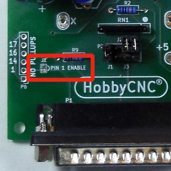
The idle current reduction has been re-designed. The “low power after 10 seconds of no signal” has been replaced with a Pin 1 enable option. Normally, the Rev 2 board is delivered with the no idle current reduction. To enable Pin 1 to control the idle current, just add a small ‘blob’ of solder on the two pads labeled J1.
Pin one needs to be configured in your software as “active high” to enable the motors at full power.
Bringing the signal low will put the motors in half power mode*

*Idle Current Reduction details
Why only half power instead of fully off? It was a ‘fail-safe’ decision. It is possible for an axis (especially the Z axis) to drop if there is no motor holding current. At half power, motors should still have considerable holding power. You can change the idle current if you wish (parts not included).
As indicated in the Idle Current Reduction section of the manual “As an alternate to the 50% reduction, substituting R2, R4, R6, R8 with a 4.7K value (not included) will allow only @30% current reduction. (3A down to 2A for example). Note that 20K would allow @75% current reduction.” If you leave these resistors out completely, then the current would reduce to zero when Pin 1 is low (at your own risk!).
Some of you might have noticed some pins by the D connector labeled “OPTO”. This is for a future add-on opto isolator board. This is not needed often, but when you are plagued by intermittent eStops or limits, an opto board can frequently solve the problem.
