I finally made some time to sit down to design-and-print a part using Autodesk Fusion 360. There is a lot to learn, but this is one very powerful CAD/CAM software. I was able to go from my design in Fusion 360 straight to my MakerBot printer software. Pretty damn sweet.
And here’s the best part – Autodesk Fusion 360 is FREE (sort of)
From the Fusion 360 Instructables page: “Free for students, enthusiasts, hobbyists, and startups”.
It’s a parametric system – which means you can define geometry based on other geometry – for instance, you could define the width of a slot to be .125 times the length. Change the length – and the width changes automatically. Takes a bit to get the hang of it, but once you do, you will never look at Sketchup the same way again!
It took me several hours to get my part designed. I have a basic working knowledge of Autodesk Inventor, so many of the concepts were familiar. The User Interface for Autodesk Fusion 360 is quite different from Autodesk Inventor. Here is part of the assembly (This is not the part I 3D printed):
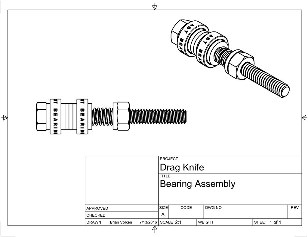
See the spring between the bearing and the hex nut? It was super easy to design – I was completely blown away. I only touched the surface of what this software can do. It is now my ‘go-to’ software for any new design.
There are some pretty cool features in the software (besides the free price), and CAM toolpath planning is built-in (haven’t tried that yet).
In the drawing above, the two bearings were CAD files downloaded from AST Bearings site, and the bolt, washers and nut were downloaded via the integrated McMaster Carr catalog.
Many of the super-powerful options that are in AutoCAD are provided in Autodesk Fusion 360. If you have the time and you are looking for a parametric-drive CAD/CAM solution, I would argue that Autodesk Fusion 360 would be a great choice.