Introduction
Below are instructions on how to install a HobbyCNC replacement fret board into your guitar.
|
There are three critical steps that must be accomplished to ensure the best possible results:
|
Equipment Needed:
- Modified (or 3D printed) fret buttons
- Sharpie
- Soldering iron
- Solder
- Philips Screwdriver
- T-10 Torx Driver
- For World Tour Xbox 360 only: T-6 Torx Driver.
Watch the video
Here is step-by-step from beginning-to-end on how to install a replacement fret board.
In the video, I put a GH-04 board into a World Tour Guitar for Wii.
Note that all the boards install using pretty much exactly the same process. Some have one screw holding the board down, some have two, some have split ribbon cables, some have one some have more wires, some have fewer. All variations on the same theme!
Open Guitar Neck to Access PC Board
Use the T-10 Torx wrench to remove the screws holding the neck together.
Screw locations may vary from guitar model to guitar model.
PRO TIP: Take some photos before you unscrew or remove the printed circuit board.
- The original circuit board. Held in place with one or two screws.
- The ribbon cable
- The circuit-board that mates to a connector in the guitar body.
The circuit board (item 1) will be replaced. Items 2 and 3 will be re-used.
Mark the cable
This is a very important step. 90% of installation problems are from installing the ribbon cable upside-down.
Do this before you remove the PC Board from the guitar.
Single Ribbon Cable: With a Sharpie mark the visible (top) side of the cable with a sharpie (“UP” in the example).
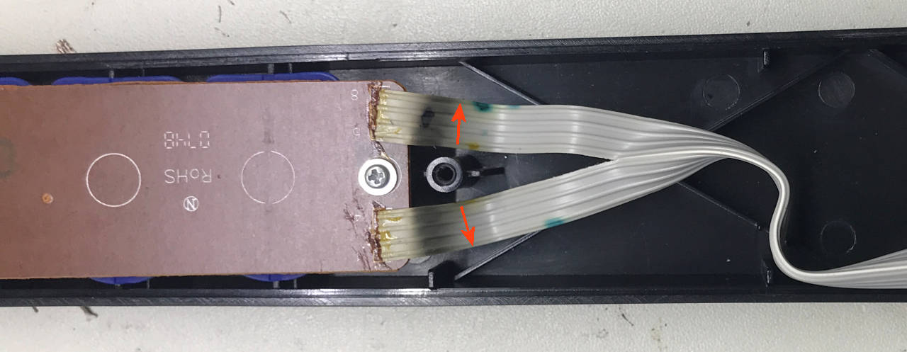
Double or Split Ribbon Cable: With a Sharpie mark the visible (top) sides of both cables with an arrow pointing toward the outside of the guitar neck as shown to the right.
It is essential that these marks be visible and in the same orientation when the new board is installed.
Watch the video above and check out Wiring Details for HobbyCNC Mechanical Fret Buttons.
Remove the PC Board and Cable
Remove the screw(s) retaining the PC board and be sure to set them safely aside.
Lift the PC board out of the guitar neck.
Notice the numbers on the PC board (red arrows). The cable will be re-soldered to the new PC board in this same order, however the wires will enter the new PC board from the “other” side.
Although the wiring will enter the ‘other side’ of the new PC board, pins are in the same place, so the same side of the cable will still be “up” as it is now.
The Fret Switch PC Board & Parts
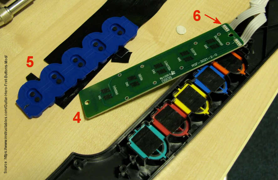
#4 is the ‘underside’ of the stock fret switch pc board. This is the side you will un-solder the ribbon cable from.
#5 is the flexible, conductive membrane that provides the ‘springy’ part of the switch and makes connection when the fret button is pushed. It will not be re-used.
#6 is where the ribbon cable is un-soldered.
Unsolder and remove the ribbon cable from the fret switch PC Board. Use care as this is stranded wire and it can get messed-up such that re-installation can be a challenge.
PRO TIP: The easiest method I’ve found is to pull gently on the ribbon cable and move the soldering iron tip back-and-forth across all the solder joints – See #6 in the image (think “harmonica”).
Modify the Fret Buttons
The new Kailh Low Profile Tactile switch sits about 1.4mm taller than the old ‘membrane’ type switch (#5 in figure 3).
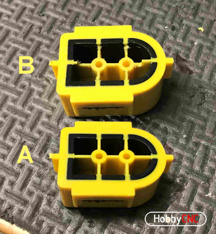
To adapt for this, I needed to mill-out 1.4mm from the underside of the fret buttons (B in Figure 6).
I have the luxury of a small mill, so it was easy for me. Whatever method you use, be sure to make every button consistent or you might end up with an ‘uneven’ feel to the fret buttons.
Cut too shallow and the button stays pressed, too deep and the button may not activate at all. Both those should be fixable!
Check out the Modify Fret Buttons page for tips and tricks on how to remove material from the back of the fret buttons.
3D Printed Fret Buttons
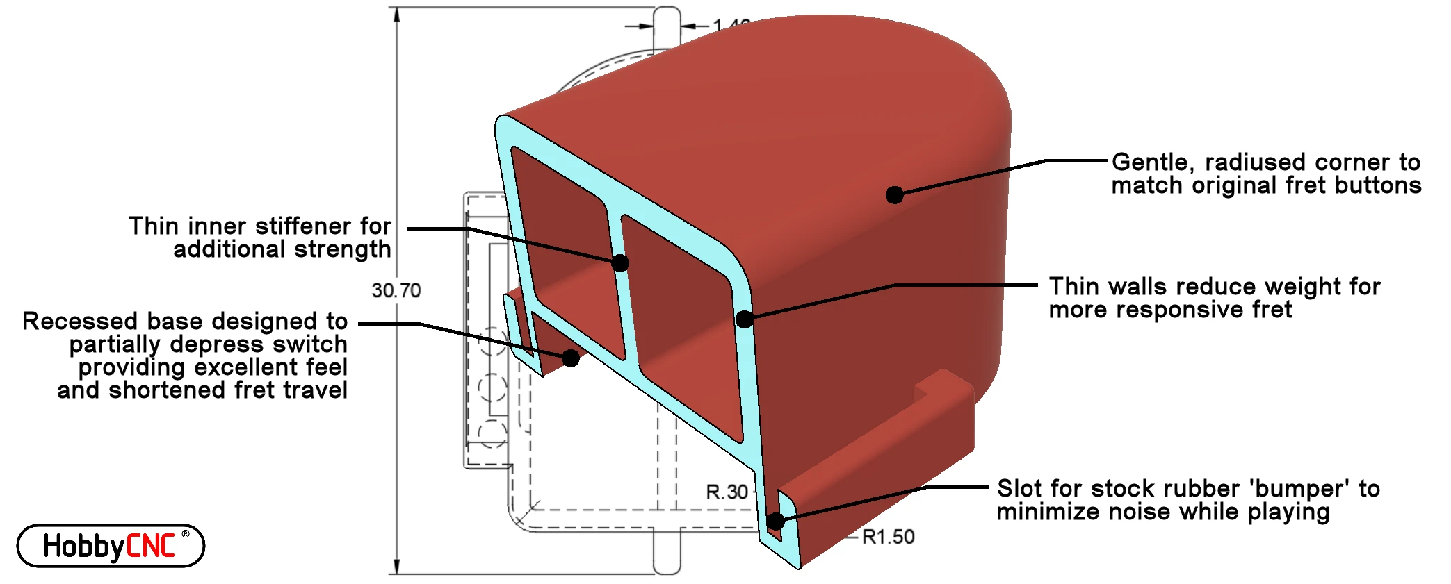
Our 3D printed fret buttons are designed to be compatible with HobbyCNC Fret Boards.
Trim the Nubs
On the underside of the switches there are small alignment ‘nubs’ (Figure 8) that fit in/through the Fret PC Board to ensure the switches are aligned properly. These ‘nubs’ protrude a small bit past the back of the Fret PC Board.
On some (most?) guitars there are strengthening ribs on the back half of the guitar neck, which ends up underneath where the Fret PC Board is installed once the neck is reassembled.
When the guitar neck is reassembled, these nubs may hit or otherwise interfere with these strengthening ribs.
Trim flush to the circuit board any nubs that align/interfere with any of the strengthening ribs.
You can watch the process here: https://youtu.be/1gbSlVd-wDQ
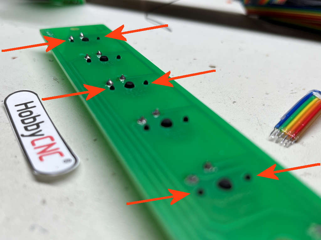
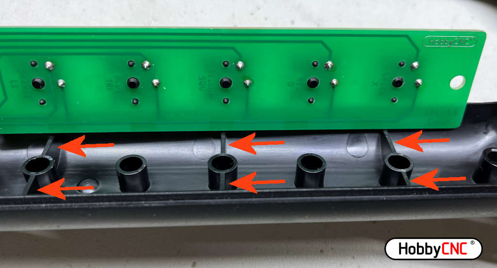
Strengthening ribs on the bottom half of the guitar neck. They are typically on the first, middle and last fret buttons. Verify on your guitar.
Reassemble
Put the modified fret buttons back in place. Use the same screws to retain the new PC board.
Verify the ribbon cable is in the original orientation.
Route the cable and re-install the connector PC board.
No changes or modifications are required to the neck of the guitar. The only mods are for the underside of the fret buttons (Figures 10 & 11.)
When I opened my guitar neck, there were already several holes in the ribbon cable (#10). Not sure if that was intentional or accidental, but either way it had no impact electrically.


