Wiring Details and Installation tips for HobbyCNC Mechanical Fret Board
The installation of the HobbyCNC Mechanical Fret Board is fairly straightforward, but there are some things that we’ve learned. Please do check also our FAQ. If more help is needed, please contact support@hobbycnc.com.
Which Side is Up?
This can be confusing, as it appears some of the connector numbering is “backwards”.
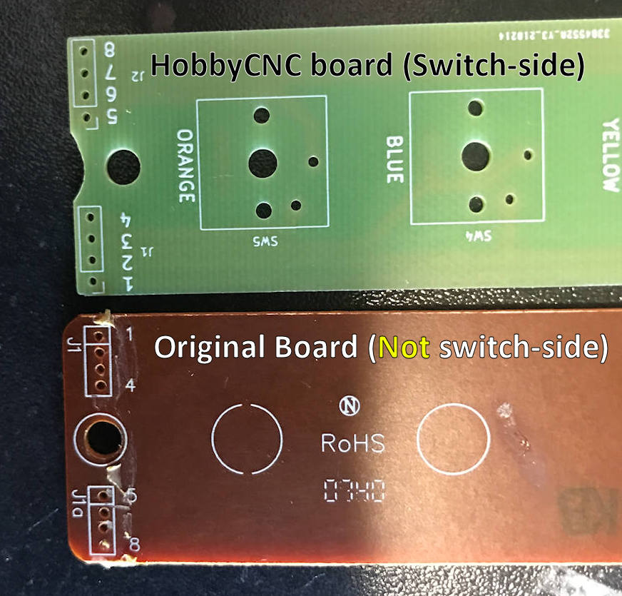
The most likely reason is that what appears to be the “top” of the boards are actually the ‘top’ of one and the ‘bottom’ of the other (see Figure 1).
For the original board, the printed-circuit wiring is on the “fret side” of the PC Board. This is because the conductive pads on the silicon switch membrane must make electrical contact to ‘close’ the circuit.
For the HobbyCNC board, the printed-circuit wiring is on the “not fret side” of the PC Board. Switches replace the silicon switch membrane, and the printed-circuit wiring needs to be on the opposite side to allow for assembly/soldering.
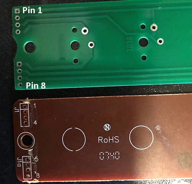
In Figure 2, both boards are oriented the same way, that is, how the boards would appear when installed, just before you close-up the neck of the guitar.
Once the HobbyCNC board is ‘flipped over’, you can see that Pin 1 is right where it belongs.
The HobbyCNC boards in Figures 1 and 2 are GH-04 boards.
That’s dumb. Why do it? Well, it’s a compromise. Silk screen is typically on the side of the board where the parts are installed. And on a single-sided PC Board, the traces are usually on the side opposite the parts. I chose to go single sided with one silk screen and one solder mask to keep the price down.

Figure 1: Labelling of HobbyCNC board (top) and OEM board (bottom).

Figure 2: Both boards oriented the same way.
Which way are the wires inserted?
This is the second assembly difference that can cause confusion.
The ribbon cable comes into the two pc boards differently – because, as discussed above, the actual circuitry is no on the other side of the board.
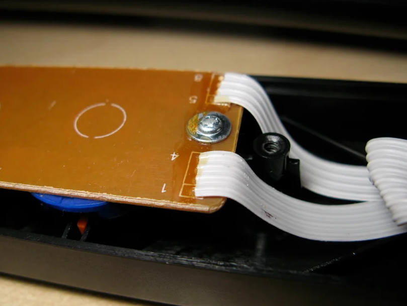
In Figure 3, you see the grey ribbon cable comes into the circuit board from the ‘top’ side.
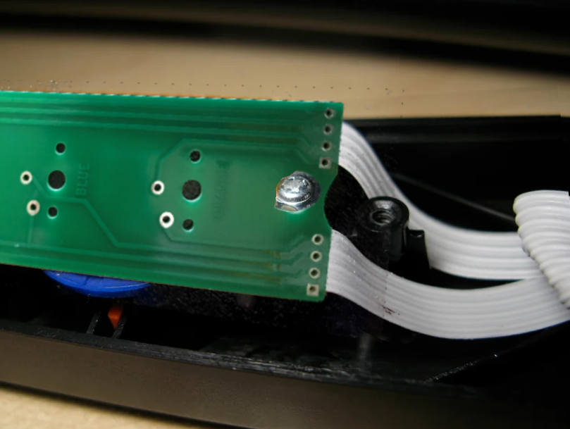
In Figure 4, I’ve photoshopped-in a HobbyCNC board to demonstrate that the ribbon cable comes in from the ‘bottom’ side now.
IMPORTANT: The ribbon cable NEVER gets flipped or twisted. Pin 1 is still in the same place it was before, the only difference is the cable pokes thru from the ‘bottom’ and is soldered on the ‘top’.
It is important to mark the cable before you remove the original board. Watch my video HobbyCNC Mechanical Fret upgrade, GH 04 install to see an install from start-to-finish.

Figure 3: Wires as connected to the original board.

Figure 4: Wires re-connected to the HobbyCNC board.
..What if the ribbon cable is reversed?
Let’s take the GH-01 board as an example.
The proper wiring of the ribbon cable is shown in Table 1 below, is a ‘truth table’ if you will, that lists out what ribbon cable connections are ‘shorted’ for each color fret button.
Table 2 is the result when the ribbon cable is wired backwards. Notice the numbers across the top are now 8 on the left and 1 on the right.
The most common symptoms of a flipped cable are:
- The wrong or no fret registers.
- Combinations of frets registers as a one or several wrong frets being pushed. Following Table 2, if Red and Yellow are pressed, the guitar will register as Blue and Red.
- Red + Yellow = 7, 2 + 7, 3 = 2, 3, 7 = BLUE (2, 3) and RED (2,7)
- Red + Blue = 7, 2 + 7, 6 = 2, 7, 6 = YELLOW (2,6) and RED (2, 7)
- In some cases, such as Green and Orange (on the GH-01) are ‘symmetrical’ so reversing the cable makes no difference.

Table 1: GH-01 properly wired. Rightmost column shows which connector pins are ‘shorted’ for each button pressed.

Table 2: GH-01 with ribbon cable reversed. Rightmost column shows which buttons the guitar will THINK you pushed.