Author: BrianV

  • HobbyCNC PRO Rev 2 Introduced

    [et_pb_section fb_built=”1″ specialty=”on” _builder_version=”4.5.0″ _module_preset=”default” custom_padding=”18px|||||”][et_pb_column type=”3_4″ specialty_columns=”3″ _builder_version=”3.25″ custom_padding=”|||” custom_padding__hover=”|||”][et_pb_row_inner _builder_version=”4.5.0″ _module_preset=”default” background_color=”#3371a3″ custom_margin=”||||false|false” custom_padding=”||||false|false”][et_pb_column_inner saved_specialty_column_type=”3_4″ _builder_version=”4.5.0″ _module_preset=”default”][et_pb_text admin_label=”Header in blue background” _builder_version=”4.5.0″ text_font=”|700|||||||” text_text_color=”#ffffff” text_font_size=”30px” custom_margin=”|||10px|false|false” custom_padding=”|||10px|false|false”]HobbyCNC PRO Rev 2![/et_pb_text][/et_pb_column_inner][/et_pb_row_inner][et_pb_row_inner _builder_version=”4.5.0″ _module_preset=”default” custom_padding=”12px|||||”][et_pb_column_inner saved_specialty_column_type=”3_4″ _builder_version=”4.5.0″ _module_preset=”default”][et_pb_text _builder_version=”4.5.0″ _module_preset=”default” custom_margin=”||0px|||”]

    I’ve made a few changes to the popular HobbyCNC PRO board. Most of the changes are cosmetic or functional, but one in particular is a big departure from the Rev1 boards.

    What hasn’t changed:

    • Roughly the same form factor (it is a little smaller)
    • Same robust, dependable driver chips
    • Same driver chip spacing as the Rev 1 (can use the same heatsink pattern)
    • Idle current reduction (implemented differently*)
    • Same PC Board manufacturer
    • Same high-quality components

    The basic changes:

    In hot pink: The power connector was turned around and moved toward the edge of the board.
    In red: I made the physical layout of all four axis identical to make assembly even easier.
    In Yellow: the unused pins are now provided in a 0.100″ layout (with ground at both ends) to allow use of a standard header.

    [/et_pb_text][et_pb_image src=”https://hobbycnc.com/wp-content/uploads/2019/02/PRO_Rev_2_with_Blocks.jpg” alt=”HobbyCNC PRO Rev 2 board with changes highlighted” title_text=”PRO_Rev_2_with_Blocks” _builder_version=”4.5.0″ _module_preset=”default” custom_margin=”||-7px|||”][/et_pb_image][/et_pb_column_inner][/et_pb_row_inner][et_pb_row_inner column_structure=”1_2,1_2″ _builder_version=”4.5.0″ _module_preset=”default” min_height=”390px” custom_padding=”4px||3px|||”][et_pb_column_inner type=”1_2″ saved_specialty_column_type=”3_4″ _builder_version=”4.5.0″ _module_preset=”default”][et_pb_text _builder_version=”4.5.0″ _module_preset=”default”]

    The big change

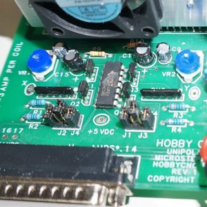
    The idle current reduction has been re-designed. The “low power after 10 seconds of no signal” has been replaced with a Pin 1 enable option. Normally, the Rev 2 board is delivered with the no idle current reduction. To enable Pin 1 to control the idle current, just add a small ‘blob’ of solder on the two pads labeled J1.

    Pin one needs to be configured in your software as “active high” to enable the motors at full power.

    Bringing the signal low will put the motors in half power mode*

    [/et_pb_text][/et_pb_column_inner][et_pb_column_inner type=”1_2″ saved_specialty_column_type=”3_4″ _builder_version=”4.5.0″ _module_preset=”default”][et_pb_image src=”https://hobbycnc.com/wp-content/uploads/2019/02/Idle_Current_Reduction.jpg” alt=”HobbyCNC PRO Rev2 showing idle current reduction enable.” title_text=”Idle_Current_Reduction” admin_label=”Image: Enable jumper” _builder_version=”4.5.0″ _module_preset=”default” custom_margin=”||-11px|||”][/et_pb_image][/et_pb_column_inner][/et_pb_row_inner][et_pb_row_inner _builder_version=”4.5.0″ _module_preset=”default” custom_padding=”5px|||||”][et_pb_column_inner saved_specialty_column_type=”3_4″ _builder_version=”4.5.0″ _module_preset=”default”][et_pb_text _builder_version=”4.5.0″ _module_preset=”default” hover_enabled=”0″]

    *Idle Current Reduction details

    Why only half power instead of fully off? It was a ‘fail-safe’ decision. It is possible for an axis (especially the Z axis) to drop if there is no motor holding current. At half power, motors should still have considerable holding power. You can change the idle current if you wish (parts not included).

    As indicated in the Idle Current Reduction section of the manual “As an alternate to the 50% reduction, substituting R2, R4, R6, R8 with a 4.7K value (not included) will allow only @30% current reduction. (3A down to 2A for example). Note that 20K would allow @75% current reduction.” If you leave these resistors out completely, then the current would reduce to zero when Pin 1 is low (at your own risk!).

    Some of you might have noticed some pins by the D connector labeled “OPTO”. This is for a future add-on opto isolator board. This is not needed often, but when you are plagued by intermittent eStops or limits, an opto board can frequently solve the problem.

    [/et_pb_text][/et_pb_column_inner][/et_pb_row_inner][/et_pb_column][et_pb_column type=”1_4″ _builder_version=”3.25″ custom_padding=”|||” custom_padding__hover=”|||”][et_pb_sidebar area=”et_pb_widget_area_2″ _builder_version=”4.5.0″ _module_preset=”default” header_text_color=”#ffffff” header_font_size=”21px” body_font_size=”12px” body_line_height=”1.6em” background_layout=”dark” custom_margin=”20px||||false|false” custom_css_widget=”background: #3371a3;||padding: 20px;|| “][/et_pb_sidebar][/et_pb_column][/et_pb_section]

  • PRO and EZ board mounting templates

    [et_pb_section fb_built=”1″ specialty=”on” _builder_version=”4.5.0″ _module_preset=”default” hover_enabled=”0″ custom_padding=”20px|||||”][et_pb_column type=”3_4″ specialty_columns=”3″ _builder_version=”3.25″ custom_padding=”|||” custom_padding__hover=”|||”][et_pb_row_inner _builder_version=”4.5.0″ _module_preset=”default” background_color=”#3371a3″ custom_margin=”||||false|false” custom_padding=”||||false|false”][et_pb_column_inner saved_specialty_column_type=”3_4″ _builder_version=”4.5.0″ _module_preset=”default”][et_pb_text admin_label=”Header in blue background” _builder_version=”4.5.0″ text_font=”|700|||||||” text_text_color=”#ffffff” text_font_size=”30px” custom_margin=”|||10px|false|false” custom_padding=”|||10px|false|false” hover_enabled=”0″]EZ and PRO Mounting Templates[/et_pb_text][/et_pb_column_inner][/et_pb_row_inner][et_pb_row_inner _builder_version=”3.25″ background_size=”initial” background_position=”top_left” background_repeat=”repeat”][et_pb_column_inner _builder_version=”3.25″ custom_padding=”|||” custom_padding__hover=”|||” saved_specialty_column_type=”3_4″][et_pb_text _builder_version=”3.27.4″ background_size=”initial” background_position=”top_left” background_repeat=”repeat”]Never really thought about it until I was recently asked the diameter of the mounting holes on the EZ board. I couldn’t remember. (FYI, 0.125″ [3.2mm] is the spec’d diameter). That got me thinking about the mounting pattern. Anyhow, I did them and if you print them at 100% you can use them as a template.

    PRO Mounting Pattern (PDF)                EZ Mounting Pattern (PDF).

    I tucked them in the Board Assembly Instructions FAQ page.
    [/et_pb_text][/et_pb_column_inner][/et_pb_row_inner][/et_pb_column][et_pb_column type=”1_4″ _builder_version=”3.25″ custom_padding=”|||” custom_padding__hover=”|||”][et_pb_sidebar area=”et_pb_widget_area_2″ _builder_version=”4.5.0″ _module_preset=”default” header_text_color=”#ffffff” header_font_size=”21px” body_font_size=”12px” body_line_height=”1.6em” background_layout=”dark” custom_margin=”20px||||false|false” custom_css_widget=”background: #3371a3;||padding: 20px;|| “][/et_pb_sidebar][/et_pb_column][/et_pb_section]

  • My brand new stepper motor won’t turn by hand!

    [et_pb_section fb_built=”1″ specialty=”on” _builder_version=”4.5.0″ _module_preset=”default” custom_padding=”20px||||false|false”][et_pb_column type=”3_4″ specialty_columns=”3″ _builder_version=”3.25″ custom_padding=”|||” custom_padding__hover=”|||”][et_pb_row_inner _builder_version=”4.5.0″ _module_preset=”default” background_color=”#3371a3″ custom_margin=”||||false|false” custom_padding=”||||false|false”][et_pb_column_inner saved_specialty_column_type=”3_4″ _builder_version=”4.5.0″ _module_preset=”default”][et_pb_text admin_label=”Header in blue background” _builder_version=”4.5.0″ text_font=”|700|||||||” text_text_color=”#ffffff” text_font_size=”30px” custom_margin=”|||10px|false|false” custom_padding=”|||10px|false|false”]Your Motor is Fine![/et_pb_text][/et_pb_column_inner][/et_pb_row_inner][et_pb_row_inner _builder_version=”4.5.0″ _module_preset=”default” column_structure=”1_2,1_2″][et_pb_column_inner saved_specialty_column_type=”3_4″ _builder_version=”4.5.0″ _module_preset=”default” type=”1_2″][et_pb_text _builder_version=”4.5.0″ _module_preset=”default” hover_enabled=”0″]Customer received some new stepper motors and found it very difficult to spin the shaft by hand. Naturally, the thought was the motors were ‘bad’. Normally, you can easily turn a stepper motor shaft by hand, and you can feel each of the 200 ‘detents’ as you rotate the shaft. However, these motors were very hard to turn by hand.[/et_pb_text][/et_pb_column_inner][et_pb_column_inner saved_specialty_column_type=”3_4″ _builder_version=”4.5.0″ _module_preset=”default” type=”1_2″][et_pb_image _builder_version=”4.5.0″ _module_preset=”default” title_text=”Stepper motor wires” src=”https://hobbycnc.com/wp-content/uploads/2018/11/Stepper-motor-wires.jpg” border_radii=”on|1px|1px|1px|1px” hover_enabled=”0″ custom_margin=”||0px|||” border_width_all=”1px” border_color_all=”#0c71c3″][/et_pb_image][/et_pb_column_inner][/et_pb_row_inner][et_pb_row_inner _builder_version=”3.25″ background_size=”initial” background_position=”top_left” background_repeat=”repeat” custom_padding=”2px|||||”][et_pb_column_inner saved_specialty_column_type=”3_4″ _builder_version=”3.25″ custom_padding=”|||” custom_padding__hover=”|||”][et_pb_text _builder_version=”4.5.0″ background_size=”initial” background_position=”top_left” background_repeat=”repeat” hover_enabled=”0″]

    Well, the motor was just fine. Here’s the deal: you can see in the image how the wiring is stripped-back at the factory for testing. Depending on which wires happen to short-together during shipping and handling, the motor can be difficult to turn, or if all the wires are touching, the motor can’t be turned by hand! Separate the wires, and the ‘problem’ disappears.

    [/et_pb_text][/et_pb_column_inner][/et_pb_row_inner][/et_pb_column][et_pb_column type=”1_4″ _builder_version=”3.25″ custom_padding=”|||” custom_padding__hover=”|||”][et_pb_sidebar area=”et_pb_widget_area_2″ _builder_version=”4.5.0″ _module_preset=”default” header_text_color=”#ffffff” header_font_size=”21px” body_font_size=”12px” body_line_height=”1.6em” background_layout=”dark” custom_margin=”20px||||false|false” custom_css_widget=”background: #3371a3;||padding: 20px;|| “][/et_pb_sidebar][/et_pb_column][/et_pb_section]

  • Blown Chip #2

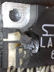
    This is a very unusual chip to blow like this. Just like with the blown driver chip, damage like this indicates a LOT of power. But this chip is nowhere near any high voltages.

    The Diagnosis

    1. Assembly error? Nope. This was an assembled PRO board, so it was fully tested prior to shipment.
    2. The board had two stepper motors connected and power added. The motor current was set and the motors locked. Good.
    3. When the board was connected to the PC, the chip blew.
    4. Primary suspect #1 – some issue with the power supply, perhaps some voltage to the chassis causing a lot of current through ground. Supply was a cheap 36V 10A Chinese switching supply, that measured 36 volts between the chassis and the V-. This seemed odd to me, I’d prefer the V+ and V- outputs to be isolated from the chassis.
      Side Note: You can see a cheap Chinese vs. quality power supply here: https://www.youtube.com/watch?v=rJ2SiBzijiw. It’s 15 minutes and worth the watch.
    5. What about the cable from the HobbyCNC PRO to the PC?

      a. The customer did not purchase the parallel cable from me.
      b. Turns out the customer purchased a serial printer cable. Only half correct. The PRO requires a parallel printer cable, all 25 pins, wired straight-through.

    So, I’m not 100% certain is wasn’t the power supply, but at this point, my money is on the use of the serial printer cable.

  • Experience is a tough teacher

    [et_pb_section bb_built=”1″ admin_label=”section”][et_pb_row admin_label=”row”][et_pb_column type=”4_4″][et_pb_image admin_label=”Image” src=”https://hobbycnc.com/wp-content/uploads/2018/06/Success_Quote-1.jpg” show_in_lightbox=”off” url_new_window=”on” use_overlay=”off” animation=”left” sticky=”off” align=”left” force_fullwidth=”off” always_center_on_mobile=”on” use_border_color=”off” border_color=”#ffffff” border_style=”solid” url=”https://www.brainyquote.com/quotes/winston_churchill_131188?img=4″ /][et_pb_text admin_label=”Text” background_layout=”light” text_orientation=”left” use_border_color=”off” border_color=”#ffffff” border_style=”solid”]

    When my children were growing up I used to tell them that “Experience is a difficult teacher; she gives the test first and the lesson afterwards“. I have found frequently throughout my career that I tend to learn the most when I fail. Mistakes are annoying and often embarrassing, however we tend to learn a lot more from them then we do from success.

    I’ve assembled dozens and dozens of HobbyCNC boards. Most without incident. Occasionally a component backwards or missing but generally the product tests out very well. This evening however testing my final board, the A axis motor wasn’t turning. The motor current setting was set at 3 Amps (0.42 volts). I could easily move the stepper motor with my fingers.

    By chance, I looked at the microstepping jumpers. I test the boards at 1:2 microstepping (J1 installed). But for the A axis on this board, I forgot to put the jumper on J1. As soon as I added the jumper, the A axis started working perfectly.

    I wonder if some of my customers might have had problems getting their axes to start turning and the problem might have been something as simple has no jumpers on the microstepping header!? Thanks to this simple mistake I’ve learned something new that will now go into my debugging FAQs!

    [/et_pb_text][/et_pb_column][/et_pb_row][/et_pb_section]

  • 1000th DIY CNC Plan Downloaded!

    I’m DIY CNC Router Plans, HobbyCNCdelighted to share that we just had the 1,000th download of our DIY CNC plans! I have such fun with my home-built machine that I wrote-up the plans, documented all the dimensions and assembled it into 72 pages of instructions! If you’re looking to get into CNC Cutting, you may want to check out madecnc.co.uk, for all your equipment requirements.

    It is a pleasure and an honor to see so much interest in our DIY CNC Plans and the simple build-it-yourself design. It is simple (plywood, aluminum angles, and skateboard bearings), but it is more than sufficient to experiment with CNC without breaking the bank.

    Revision 3 of our DIY CNC Plans is in the works now (Update: Rev 3 DIY CNC Plans are released!) with:

    • dimensions in imperial and metric
    • all drawings moved to Fusion 360
    • Bill of materials consolidated into one large BOM
      (was one BOM per section/assembly)

    I’m planning to make the CAD drawings available for purchase also, if you want to modify the design.

    Thanks to everyone who downloaded our plans!

  • PC Board with Solder Mask

    [et_pb_section bb_built=”1″ admin_label=”section” custom_padding=”0px|0px|0px|0px”][et_pb_row admin_label=”row” custom_padding=”0px|0px|0px|0px”][et_pb_column type=”1_2″][et_pb_text admin_label=”Text” background_layout=”light” text_orientation=”left” use_border_color=”off” border_color=”#ffffff” border_style=”solid”]

    One of the things I like to use my DIY CNC router for is to make PC boards using the isolation routing technique. My latest prototype is Isolation routed PCB with solder mask for an opto isolator board to be used with the HobbyCNC Pro when the user experiences “false triggers” of their limit or home switches. I don’t encourage or use shielded wiring (see my post To Shield or Not To Shield (your wiring). But when nothing else works, this opto board will solve the problem.

    This time I tried the addition of a dry film solder mask. This is my first attempt after some testing to figure out the time under the UV light (30 seconds in my case). It’s not quite perfect, but it is good enough for now. Holding the artwork down against the board with some glass will help, and having a black background below the board seems to help too.

    [/et_pb_text][/et_pb_column][et_pb_column type=”1_2″][et_pb_image admin_label=”Image” src=”https://hobbycnc.com/wp-content/uploads/2017/12/Dry_Solder_Mask.jpg” alt=”Dry Film Solder Mask, HobbyCNC, DIY CNC Router, PCB isolation routing” animation=”off”]
    [/et_pb_image][/et_pb_column][/et_pb_row][/et_pb_section]

  • The Power of Checklists

    [et_pb_section bb_built=”1″ admin_label=”section” custom_padding=”0px|0px|0px|0px”][et_pb_row admin_label=”row” custom_padding=”0px|0px|0px|0px”][et_pb_column type=”2_3″][et_pb_text admin_label=”Text” background_layout=”light” text_orientation=”left” use_border_color=”off” border_color=”#ffffff” border_style=”solid”]

    I’ve started using checklists. A few nights ago I made a small, careless mistake and wrecked one of my nice 60 degree milling bits (at $14 a pop).

    My ‘favorite’ mistakes include:

    • restarting LinuxCNC and forgetting to reload my program
    • forgetting to connect the probe wiring before running the autoleveller
    • Jogging an axis with the motors powered-off (losing my home)
    • Leaving the probe wiring connected so I get a probe error as soon as the tool touches the workpiece.

    So, in the interest of saving time, money, parts and frustration, I finally created a basic checklist. I keep thinking “this is easy, I’m pretty good at it”. Followed by the sound of a axis reaching it’s torque limit.

    I set up the checklist in three parts: Setup, milling, cleanup. This particular example is for isolation-routing PC boards.
    I put the page in a plastic sleeve so I can use a whiteboard marker and erase it when I’m done.

    So far, so good. Now I need a checklist to remind me that I’m not smarter than the checklist.


    [/et_pb_text][/et_pb_column][et_pb_column type=”1_3″][et_pb_image admin_label=”Image” src=”https://hobbycnc.com/wp-content/uploads/2017/09/milling_checklist.jpg” alt=”Pre-milling checklist example – HobbyCNC” title_text=”Checklist example” show_in_lightbox=”on” sticky=”on” /][/et_pb_column][/et_pb_row][/et_pb_section]

  • Where has all the power gone?

    Making sure your stepper motor wiring is robust and secure is critical. Most (all?) stepper motor driver instructions include the warning “do not connect/disconnect motors while power is applied”. Curious why?

    A brief-yet-incomplete intro to stepper motors is appropriate. Stepper motors contain several windings. These windings are very large inductors. By their nature, inductors a) resist changes in current flowing through them and b) store energy in the magnetic field they create.

    Steppers are often rated at a very low voltage and fairly high current – like 3 Volts and 3 Amps per winding. Yet we suggest a very large power supply, at 36 Volts (or more depending on the driver). My board (and most others) energize a winding by slamming (a technical term) the voltage to the winding and monitoring the current flow. When the current hits the max setting, the board backs-off the voltage, in my case by using a chopper technique – often you can hear the motors ‘whine’ at the chopper frequency.


    [one_half]
    As the current begins to flow in the winding, a LOT of energy is stored as a magnetic field around the winding. When that winding is turned-off, that magnetic field collapses quickly, in turn generating a lot of power – and this power needs to be dissipated (typically as heat) by the driver board. So far, so good.

    So what happens when you mess with the wires while the motor is powered-up? Here’s one example. Take a close look at the solder joint in Figure 1. This is the common for the a-A winding at the terminal strip for the x-axis. The solder is hanging onto the pin, but not making good contact to the PC board trace. It worked for an hour-or-two. At some point, this connection opened-up.

    Remember all that power stored in the winding? It’s going somewhere. Since it couldn’t go through the common pin, it had to go through the driver chip – causing enough heat to blast-off a chunk of the driver IC.

    For the record, this is NOT covered by warranty.

    Pro Tip: Make double-sure your power supply is at zero volts before you mess with any stepper motor wiring!
    [/one_half]

    [one_half_last]
    Bad Solder Joint

    Figure 1. Bad solder joint (magnified 40x)

    Blown Chip

    Figure 2. Blown driver chip
    [/one_half_last]

  • We all make misteaks

    [et_pb_section bb_built=”1″ admin_label=”section”][et_pb_row admin_label=”row”][et_pb_column type=”1_2″][et_pb_text admin_label=”Text” background_layout=”light” text_orientation=”left” use_border_color=”off” border_color=”#ffffff” border_style=”solid”]

    I recently assembled 5 PRO 4-axis boards. I’m pretty careful. I follow directions. I am quite familiar with the boards.

    Only 60% (three out of five for you non-math types) worked first time! Oh the shame.  Careful(er) visual inspection revealed the problems:

    • One board, I neglected to solder one of the pull-up SIP packages.
    • Other board (image to the right): I had one electrolytic capacitor in backwards (they don’t like that). It was quickly replaced.- You can’t just turn them back around the right way, you’ve got to replace them!

    The moral of this story is pretty clear and is consistent with my years in tech support – the majority of problems can be found with careful visual inspection. Yes, I did use magnification to check all my solder joints. All my soldering was perfect. Nevertheless, both of the issues I had were found without anything but my eyes.

    * Kudos to everyone who caught the intentional spelling error in the blog title.

    [/et_pb_text][/et_pb_column][et_pb_column type=”1_2″][et_pb_image admin_label=”Backwards_Cap” src=”https://hobbycnc.com/wp-content/uploads/2017/07/Backwards_Cap.jpg” show_in_lightbox=”off” url_new_window=”off” use_overlay=”off” animation=”off” sticky=”off” align=”left” force_fullwidth=”off” always_center_on_mobile=”on” use_border_color=”off” border_color=”#ffffff” border_style=”solid” /][/et_pb_column][/et_pb_row][/et_pb_section]