KiCAD –> FlatCAM –> Auto-leveling –> Isolation Routing
KiCAD –> FlatCAM –> Auto-leveling –> Isolation Routing Single-Sided PCB
Here is my process for getting from a PC board design in KiCAD to an isolation-routed PC board on my DIC CNC Router. These instructions are for a single-sided board. When I get to my next double-sided board, I’ll document the process there too.
Introduction
Using breadboards for prototyping (Figure 1, left) is great for your initial circuit design. These are super-flexible and allow for easy and frequent design changes. However, this type of design is not sufficient for placing your circuit into use in the ‘real world’.
Wiring circuits on a perf board (Figure 1, right) is time consuming and rarely ‘pretty’. Wire wrap is a thing of the past. Both perf board and wire wrap are effective techniques, however both can be difficult to troubleshoot.
PCBs (Printed Circuit Boards) are the clean-looking and sexy way to make a circuit. For prototype PCBs, you can use a chemical etching approach. Getting a good etch using laser transfer and harmful and messy chemicals is part art and part science. The chemical can be caustic, dangerous and messy.
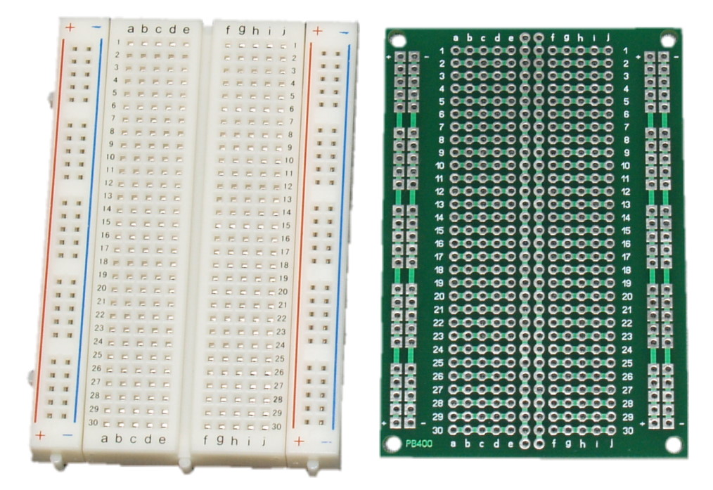
Figure 1. Breadboard (Left) and Perf Board (Right)
I have been making my own circuit boards with my HobbyCNC DIY CNC machine. I have had excellent results using this technique. There are no messy chemicals.
I’ve done the chemical etching, and the results are very good, but then you’re left with having to hand-drill all those holes.
The Bonus Feature for CNC Routing a PCB
One almost-always-overlooked benefit to using a CNC router is drilling the holes. It is a major pain-in-the-ass to manually drill the holes with a drill press, especially if there are 100’s of holes, which is not unreasonable even on a surface mount (SMT) board! With the CNC, the holes are dead-nuts-on, every time, all the time. In addition to being far more accurate than hand-drilling, it takes waaaay less time than hand drilling.
Tool Chain
Most of these products are free or very low cost. This is in keeping with my overall goal of making CAD/CAM accessible to hobbyists!
| KiCad | kicad-pcb.org | A Cross Platform (Windows, Linux, Mac) and Open Source Electronics Design Automation Suite. Schematic capture, PC Board layout, 3D viewer. |
| FlatCAM | flatcam.org | Convert Gerber and Excellon files (from KiCad) into G-code. Isolation routing is one of many tasks that FlatCAM is perfect for. |
| Autoleveller | AutolevellerAE | Autoleveller helps here by varying the depth of the tool during the milling process. The copper is very thin, and you only want to cut off just what you need. |
| CamBam | www.cambam.info | CamBam is an application to create CAM files (gcode) from CAD source files or its own internal geometry editor. Not free. Used to evaluate gcode files before committing to the mill. |
| LinuxCNC | LinuxCNC.org | LinuxCNC controls CNC machines. It can drive milling machines, lathes, 3d printers, laser cutters, plasma cutters, robot arms, hexapods, and more. |
The Design for this Example
For this example, I’ve designed a simple pulse-to-current converter (tachometer). It accepts input pulses and converts them to a fixed pulse width (the 555 timer) which is then integrated (R7, C7) and that drives a current source (Q1 & R9) to drive the meter.
I prototyped on a breadboard. I’m converting to this first-pass PC Board for continued testing, including testing in my garage, so I need something more durable.
Since it’s for test only, there are no mounting holes in this version (it needs a special ‘footprint’ to fit into the tachometer housing)

Figure 2. Schematic (KiCad) used in this example. Click for larger PDF.