PC Board milling (Isolation Routing)
Autoleveller
Introduction
Air cuts are an annoying problem when milling PC boards. We only want to remove 2 mils (2 thousandths of an inch or 0.002 inches) of copper plus just a touch of the underlying fiberglass.
This means your bed must be perfectly level and the PC board must also be perfectly flat. If you’re off by even half a mil (0.0005 inches), you might leave copper that would need to be manually removed or lead to shorts.
Since my DIY HobbyCNC router is good, but not that good, I use a program called an autoleveller. Regardless of the qualify of your mill, there are too many variables (bed level, backlash, pcb mounting) I’d still suggest autolevlling. It saves more grief than you can imagine.
Autolevlling uses the probe signal/feature to test the “real” Z zero level at pre-determined points around your board. These “delta Z” values are saved and added-to the z-axis as the board is being milled.
Mill setup
You will need to reference your documents and set up your machine for a probe. You will also need to define the probe in signal in your CAM software.
Be double-damn-sure to verify that the probe signal is working properly every time before you start milling!!
Since the autoleveller depends on a probe signal (e.g. electrical current flow between the probe and the PC board), you must use a new pc board with no holes or traces to interfere with the continuity of the probe signal during probing. If doing a double-sided board, this means milling traces on both sides before you drill holes!
Per the instructions, for probing, I use the same tool that I plan to mill the PC Board with. This avoids the need to change the tool and the potential to introduce some new problems.
PC Board mounting and preparation for isolation routing
-
- Prepare a flat sacrificial board. I use a small piece of MDF (like 9 x 12″).
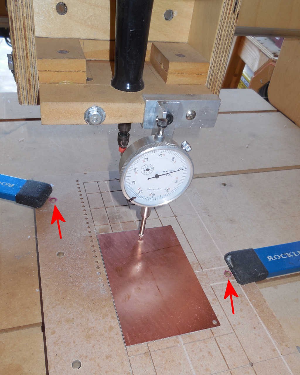
- Add three levelling screws in a ‘tripod’ formation (two of these can be seen in Figure 1 – red arrows).
- Mount your PC Board to the sacrificial board. My new approach is to weight-down the board and put a glob of hot-glue at each corner and some on each side (no glue goes under the board).
- Using a dial indicator attached to your z-axis, adjust the three leveling screws to level the PC board as well as you can. Within one-or-two thousandths is my target.
REALLY IMPORTANT
The PC Board MUST be mounted well to the sacrificial board. I tried double-sided tape, corner clamps, edge clamps, but I settled on hot glue. If there is ANY flex in the PC board, you will end up with air cuts. I put a few dabs of hot glue at each corner and a few dabs along each edge. I’ve had zero problems using this trick.
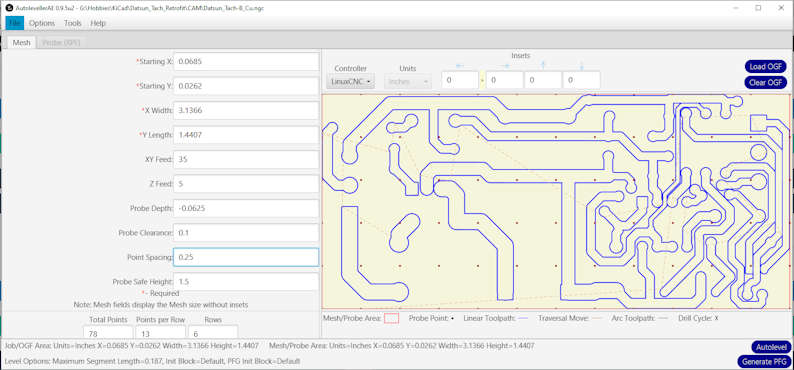
Open the Autoleveller software
Load OGF (Original Gcode File) and select the top or bottom gcode files (ending in _Bottom_Mill.ngc and Top_Mill_ngc”.
Check the XY Feed and Z Feed to be consistent with your system.
Probe Depth is the ‘fail safe’ maximum distance below Z=zero that the probe will go if no probe signal is received. This prevents damage to your PC Board and tooling (been there, done that).
Probe Clearance is how high above the copper level the tool will rise between probe points. Smaller = better.
Point Spacing is the distance between probe points. I have settled on 1/4″ with good results. More probe points = more time required to probe the board.
Probe Safe Height the retract distance before-and-after probing for tool changes (I don’t change tools between probing and milling)
Push Autolevel to create a new, autolevelled gcode file.
Probing
Here’s what probing looks like. Pretty boring, but all inconsistencies in the surface of the PC Board are being recorded. These probe points will be used to ‘adjust’ the Z axis during milling.
You need to ensure that you have your CAM software set to have a probe input. You need to ensure that you have electrical continuity between your probe and the PC board surface.
The white plastic pipe in the right-background is weighted and a sewing needle provides the electrical connection to the PC board copper. The probe is grounded through the body of the spindle (although this approach is not recommended, it’s been working well for me)
Video 1 – probing in process.

