Category: HobbyCNC Blog

HobbyCNC Blog

  • Eagle and Autocad

    [et_pb_section bb_built=”1″ admin_label=”section”][et_pb_row admin_label=”row” make_fullwidth=”off” use_custom_width=”off” width_unit=”on” custom_width_px=”1080″ custom_width_percent=”80″ use_custom_gutter=”off” custom_padding=”0px|||” allow_player_pause=”off” parallax=”off” parallax_method=”on” make_equal=”off” parallax_1=”off” parallax_method_1=”off”][et_pb_column type=”4_4″][et_pb_post_title admin_label=”Post Title” title=”on” meta=”on” author=”on” date=”on” categories=”off” comments=”on” featured_image=”off” featured_placement=”below” parallax_effect=”off” parallax_method=”on” text_orientation=”left” text_color=”dark” text_background=”off” text_bg_color=”rgba(255,255,255,0.9)” use_border_color=”off” border_color=”#ffffff” border_style=”solid” /][et_pb_text admin_label=”Text” background_layout=”light” text_orientation=”left” header_font_size=”30″ header_font_size_tablet=”30″ header_font_size_phone=”30″ header_letter_spacing=”0″ header_letter_spacing_tablet=”0″ header_letter_spacing_phone=”0″ header_line_height=”1″ header_line_height_tablet=”1″ header_line_height_phone=”1″ text_letter_spacing=”0″ text_letter_spacing_tablet=”0″ text_letter_spacing_phone=”0″ text_line_height=”1.7″ text_line_height_tablet=”1.7″ text_line_height_phone=”1.7″ use_border_color=”off” border_color=”#ffffff” border_width=”1″ border_style=”solid” custom_margin=”5px|||”]

    One thing I use my DIY CNC machine for is milling PC Boards (it’s technically called “isolation routing”). This is fairly fast, inexpensive, accurate and uses zero nasty chemicals.

    I’d been using Eagle Schematic & PCB design software. Great product, works very well, I like it a lot.

    Then Autodesk bought Eagle. I liked the idea of Eagle belonging to the Autodesk family (AutoCAD, Autodesk Inventor, Fusion 360 and many more). Autodesk is a great company, with equally great products.

    But here’s the rub

    Autodesk changed the licensing to a subscription model. So for the hobbyist, like me, I now have to shell out $100 USD per year. I don’t use it enough to justify this ongoing expense.

    HobbyCNC Opto Isolator Board prototype mockup
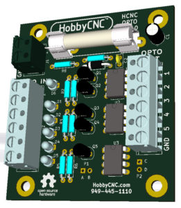
So I’m trying KiCAD. It’s free. This is good. It seems to have good community support. The core concepts are the same as any schematic capture software, but the implementation is different. KiCAD is different enough from Eagle that there is some learning involved. Nevertheless, I got a working schematic in and a PC Board designed. KiCAD has a built-in 3D viewer which I found to be super-cool.

    Next I need to export the Gerber and drill files into FlatCAD which will in-turn produce the necessary G-Code for milling. I’ve got my new Tapered-stub End-mill PCB Traces-isolation Bits from Think-and-Tinker/Precise Bits.

    I’ll provide an update once I get a board milled.

    [/et_pb_text][/et_pb_column][/et_pb_row][/et_pb_section]

  • What’s all this about BreakOut Boards (BOB)

    A BreakOut Board – a BOB for short, takes an input, typically from a computer or a ethernet/USB-to-parallel converter and splits up the signals into individual pins. These pins are then wired to individual stepper driver boards.  Most stepper driver boards require two signals to make the stepper motor move – Step and Direction.

    Example of a BOB Break out board - HobbyCNC
    Figure 1 – a typical BOB

    Also, like the board shown in Figure 1, there are opto isolators. These are to electrically isolate your computer from the stepper motor drivers. For most hobby installations, opto isolation for the stepper motor drivers is not necessary. There are cases where opti isolation makes great sense, like in more industrial environments where different machines at potentially different ground levels can cause havoc.  I’ve personally seen this destroy unprotected electronics. See Ground Loop. It would be highly unlikely for a large ground potential to exist within a single piece of equipment.

    Some BOBs can include LEDs on some of the lines – and this can be very handy during installation and debugging.  BOBs can also include other features, but then they really aren’t BOBs anymore.

    [one_half]Positives:

    • Opto isolation (belt-and-suspenders)
    • LED lites on some lines (maybe)
    • Can possibly support more than 4 axis
    • Looks impressive

    [/one_half][one_half_last]Negatives:

    • Opto isolation is not necessary
    • Higher parts count – a whole extra board, components and LOTS of extra connections and wiring
    • More complicated wiring
    • Extra cost

    [/one_half_last]

    Compare to HobbyCNC boards:

    A BOB is not required for any of our boards.  We put 3 or 4 drivers onto one board, and we route the wiring from the DB25 connector to the driver chips without the need of any additional circuitry. This provides a one-board solution with – zero extra wiring – for up to 4 axis – compared to 5 boards for a 4-axis BOB-based solution.

    Wiring diagram BOB 4 axis - HobbyCNC
    Figure 2 – typical wiring for a BOB with 4 axis.

    Figure 2 shows the wiring for a typical BOB and 4 driver modules. It’s not rocket science, but as my engineer friend says “a key role of an engineer is to take out as much as possible, but no more”.  If it can be done as good – or better – with fewer parts, less wiring, reduced complexity – then that is a win.

    Of course, all that wiring and all those modules look really impressive, but that’s not why most of us are in this hobby!

    As my daddy used to say “Keep It Simple, Stupid”.

  • The lowest price DIY CNC electronics isn’t always the best value

    Cheap-ass Chinese stepper driver board
    Figure 1 Cheap-ass Chinese stepper driver board

    Is cheap electronics a good value? It depends if you decide to play around with it using online tools like Upverter.com to arrange your schematic to ensure that the cheaper parts can deal with the electrical loads correctly. In this case, “Value” means the benefit you receive vs. the price you pay. The simplest form of this equation says, pay the lowest price you can find, and this will increase the value to you. However, the formula isn’t that simple. You need to factor in quality and support too. Unfortunately, you may find that you’re more likely to need Fanuc Servo Motor Repair if you decide to buy cheap electronics that are relatively low in quality.

    Regarding the electronics to drive your Hobby CNC stepper motors, there are LOTS of cheap (and I mean that in the least-nice-way possible) Chinese controller boards from Alibaba. Figure 1 is just one of many for around $10 for one axis.

    Right off the bat – something smells wrong. How can they do it so cheap? Well, here’s the answer: Use the cheapest-crap parts you can find from any bin you can. Parts that don’t meet spec, electrolytics that dry-out and fail, questionable assembly quality. Every quality corner that can be cut, is cut.

    Figure 2 - Cheap, crap electrolytic capacitor
    Figure 2 – Cheap, crap electrolytic capacitor

    Proof Point: in Figure 1, everything is covered by a heatsink, but you can clearly see one electrolytic capacitor (enlarged in Figure 2).

    Chengx. Ever heard of them? Me neither. Google “Chengx capacitor quality”. Not good news.

    Here’s a great video ‘teardown’ of some knock-off Chinese crap electronics by Dave Jones of the EEVBlog. jaycar-dmx-rgb-led-lights-teardown/. You will see an excellent example of just how many corners can be cut, how much cost can be carved-out.

    So, quality is highly questionable, “I’ll just buy 5 of them to have a spare-or-two – that’s still only $50!”

    Besides low/no quality parts, dicey assembly practices and no/low quality service, consider who you are going to call if there are any problems? Nobody, that’s who. You can post on a forum and hope someone else has already figured out the problem. Your time ain’t free.

    You will also need a breakout board (BOB). And a 5V power supply.

    So where are we:

    5 boards @ $10 each ($50) + BOB @ $10 + 5V power supply @$5. So you can have the lowest quality, cheapest, most unreliable, unsupported, poorly documented solution for $65.

    HobbyCNC PRO 3 axis is $76. All quality parts, no knock-offs, no grey market, no ‘generic’ parts. No BOB required and no extra +5V supply – giving you simplified wiring as a bonus.

    Think about it.

    Additional Viewing

    CapXcon capacitors (another ultra-cheap Chinese capacitor) EEVblog #347 – Bad Cap LCD Monitor Repair

    EEVblog #365 – ESR Meter Bad Cap Monitor Repair

    Toms Hardware, PSUs 101: A Detailed Look Into Power Supplies, Capacitors Manufacturer Tier List (Note: I only use Panasonic or Suncon)

  • The Art of Remote Troubleshooting

    “My X axis stopped working. What’s wrong?”

    I was in pre-and post-sales technical support professionally for about 20 years of my career. I’ve provided support over-the-phone, in the shop and in the field. I consider myself to be pretty good at the process of systematic troubleshooting.

    My daddy used to say “If you drop your car keys in the street at night, look under the streetlights first, because it’s easiest” and “The best place to start is at the beginning“. The takeawayalways check the easiest or most obvious things first.

    This “obvious things first” approach can sometimes be offensive to the customer. Questions like “is it plugged in?” and “is the power switch on?” are good and realistic places to start, but it sometimes leaves the customer wondering if I think they are brain-dead.  Check the simple things first.

    The problem of remote troubleshooting is compounded because it is over the phone. You can’t see it, touch it, smell it (yes, smell it – burnt parts have a unique and obvious scent). Often the customer is not an electronic technician, may not have the proper diagnostic equipment – or even know how to use a voltmeter.

    There is a logical flow to troubleshooting in general, and this is even more important over the phone. Depending on the problem, the steps may be different, but they are all important. For example, if only one axis is ‘out’, then I would not suspect the power supply circuit – whereas if none of the motors were moving, the power supply is the first thing I would look into.  Regardless of the questions –  I need to know the answers in order to move to the next step.

    “Yeah, I checked all those” is a too-typical answer to “what are the voltages at the 5V test point, the Fan Connector and the Input Connector?“. When I get real numbers as answers, it tells me A) things are good/not good and B) you really did check them.

    The customer has to be my eyes and ears (and nose). Work has to be done to identify the failure. Read the troubleshooting steps (in the FAQs) and tell me the answers to each step. This will get us both to the solution, faster!

  • Unipolar vs. Bipolar stepper motors

    Why does HobbyCNC use unipolar stepper motors?

    And what is the difference between bipolar and unipolar stepper motors?  Is one better than the other? Let’s start with the differences between the two types of motors*.

    HobbyCNC unipolar stepper motors - Stepper Motor Exploded View
    Stepper Motor Exploded View
    (Source: http://jssmotor.en.made-in-china.com/product/rvkmWoRMZIcB/China-2-Phase-1-8-Degree-NEMA-34-Stepper-Motor-86HS118-6004A-.html)

    unipolar motor works from a single polarity on each coil.  These require simpler electronics to drive.  However, they require two pairs of windings, wired in reverse of each other.  To oversimplify, power one coil and the magnet is North-South.  Power the other coil and the magnet is now South-North.  (or “suck” and “blow” as one of my college instructors used to say).  Unipolar motors have 5, 6 or 8 wires.  More wires = more complexity to connect.  Not substantial, but more complex compared to 4 wires.

    bipolar motor has just a single pair of windings, and the electronics to drive them must be able to switch polarity, typically with an “H bridge” driver circuit.  Since the motor has only one pair (two) windings rather than two pairs (4 windings), a bipolar motor of the same weight could theoretically have more power. Bipolar motors typically have 4 wires and are therefore less complex to connect.

    Cost-wise both motors are similar.  The bulk of a motors weight comes from the body (stator assembly) and the rotor, not the wiring.

    So, why does HobbyCNC use unipolar stepper motors?

    Well, it’s not really about the motors.  It’s about the driver chip (Allegro Microsystems SLA7078MPR).  It is a mature, robust, easily ‘heat-sinkable’, durable driver chip. It has built-in short-circuit protection. It is a very reliable chip. It is priced very well for the hobby CNC market and helps us keep the cost down. It is also easily soldered, which is important since we only sell kits. We have been using this chip for many, many years, in 1000’s of boards, with outstanding success.

    And, from a practical standpoint, 8 wires isn’t all that complex to handle.  Really.

    To learn a bit more, there is an excellent article on Adafruit.com with drawings and great images.


    * This is not meant to be a complete tutorial on stepper motors.  There are many types and designs of motors, many sizes and many price ranges. This description is kept basic for common, simple stepper motors to be used for hobby-level machines.

  • Drive screws – 1/4-20 threaded rod vs. Acme screw

    I have been thinking about my decision to use a 1/4-20 threaded rod to drive the axis instead of an acme screw. The answer is the typical engineering answer: “trade-offs”. Threaded rods can be a very valuable tool for a lot of building projects, and you might want to take a look at a page like https://tradefixdirect.com/threaded-rod-studding if you need one for a project you’re working on.

    The primary goal of my HobbyCNC plans is to provide a functioning 3-axis router, with reasonable performance, using common materials, within the budget of a hobbyist. Whilst many people want to consider getting a router for router table (which is likely the smarter idea), this build will provide an excellent foundation for learning the spectrum from design through machining.

    1/4-20 ‘all thread’ threaded rod

    On the positive side – it is inexpensive and readily available (at least in the U.S.). I’m sure metric versions are easily available outside the US.

    On the negative side – it takes 20 turns to move one inch. This means a big sacrifice in axis movement speed. I reliably get 30 ipm. I haven’t tried to push it, but I have reached 48 ips, but not in production. Also, if you get past 3 feet (approx 1 meter) or you get the speed up too high, this thin rod can ‘whip’ and create an unpleasant knocking sound.

    FWIW, I use 1/4-20 drive screws on my machine. Works great for wood, plastic, PC board isolation routing and engraving aluminum.

    Acme screws

    On the positive side – typically larger diameter (less/no whipping), high accuracy, precision machined, fancy ball-bearing nuts available. Also fewer threads-per-inch you can get much faster axis movement!

    The downside: Cost. These are at least an order of magnitude more expensive. Like $100 per axis instead of $10. (prices vary widely, don’t nit-pick me).

    If you want to go with Acme screws, please do. If your primary focus is to learn and experience machining on a budget, stick with the 1/4-20.

  • Autodesk Fusion 360

    I finally made some time to sit down to design-and-print a part using Autodesk Fusion 360. There is a lot to learn, but this is one very powerful CAD/CAM software. I was able to go from my design in Fusion 360 straight to my MakerBot printer software. Pretty damn sweet.

    And here’s the best part – Autodesk Fusion 360 is FREE (sort of)

    From the Fusion 360 Instructables page: “Free for students, enthusiasts, hobbyists, and startups”.

    It’s a parametric system – which means you can define geometry based on other geometry – for instance, you could define the width of a slot to be .125 times the length.  Change the length – and the width changes automatically.  Takes a bit to get the hang of it, but once you do, you will never look at Sketchup the same way again!

    It took me several hours to get my part designed.  I have a basic working knowledge of Autodesk Inventor, so many of the concepts were familiar.  The User Interface for Autodesk Fusion 360 is quite different from Autodesk Inventor.  Here is part of the assembly (This is not the part I 3D printed):

    HobbyCNC Autodesk Fusion 360 Sample Part

    See the spring between the bearing and the hex nut?  It was super easy to design – I was completely blown away.  I only touched the surface of what this software can do.  It is now my ‘go-to’ software for any new design.

    There are some pretty cool features in the software (besides the free price), and CAM toolpath planning is built-in (haven’t tried that yet).

    In the drawing above, the two bearings were CAD files downloaded from AST Bearings site, and the bolt, washers and nut were downloaded via the integrated McMaster Carr catalog.

    Many of the super-powerful options that are in AutoCAD are provided in Autodesk Fusion 360.   If you have the time and you are looking for a parametric-drive CAD/CAM solution, I would argue that Autodesk Fusion 360 would be a great choice.

  • Dangerous Wiring of your DIY CNC Controller

    Dangerous Wiring. Every time I talk or write about mains power (110/120 VAC in the US, 220/240VAC overseas) I always include the disclaimer that this voltage can injure or kill. Don’t play around.

    [stextbox id=”warning”]Mains Power Can Kill[/stextbox]

    I found this photo of a very nice, neat, well organized cabinet. I was impressed. But something caught my eye. Looking on top of the power supply, I saw something that made me shake my head. Two ‘wall wart’ power supplies were placed prong-to-prong and the mains power is connected to them via a bolt and nut securing the prongs together.

    There is so much wrong with this approach that it’s not worth even discussing.

    +1 point for clever, -100 points for dangerous. Drop a screwdriver on there and you’ll have some awesome fireworks!

    Dangerous wiring DIY CNC, DIY CNC Router Wiring
    Don’t mess around with mains voltage! [source: unknown]
    It would only have taken a few minutes more for this builder to do this in a far safer way. All the other work here is neat and organized – very nicely done.

    If you need access to mains power inside your cabinet, I would suggest ‘drawn metal box’ (also called a ‘handy box’). Use a metal cover. There are many metals that you can choose from, such as Brass, Stainless Steel, and Aluminum, which you can get from somewhere like Aluminium Warehouse (view our products at aluminiumwarehouse.co.uk/aluminium) for more information. These metals may be a good choice for your project but always check with a professional first and always ensure that you have the right equipment before starting, like a strain relief. The whole thing will cost you less than $3.00. It is safe and reliable. You can add two outlets or four outlets. You can have them switched from different sources. Why not hire test equipment to make sure that your connection is safe and reliable.

    But most importantly, the mains power is safely behind solid metal. Be smart, stay alive.

    All metal handy box - Dangerous wiring DIY CNC, DIY CNC Router Wiring
    All metal handy box (2 gang)

    Strain Relief - Dangerous wiring DIY CNC, DIY CNC Router Wiring
    Strain Relief

    Metal outlet cover - Dangerous wiring DIY CNC, DIY CNC Router Wiring
    Metal outlet cover

    Duplex Outlet - Dangerous wiring DIY CNC, DIY CNC Router Wiring
    Generic duplex outlet (US, 110/120 VAC)