HobbyCNC Tech Tips: PRO Rev1 Enable Signal Hack
Background
The HobbyCNC PRO Revision 1 board includes a feature to reduce motor current (Idle Current Reduction) when no step pulses are received after 20 seconds.
The idea is great, and it works (mostly) well. Users report lost steps when coming out of the reduced idle current mode if their step rate is too fast.
The preferred solution is to allow your CAM software to drive the “Amplifier Enable” signal to put the motors into low-or-full power modes.
HobbyCNC PRO Rev 1 “Amplifier Enable” Hack
I’ve had several users ask if it’s possible to convert their PRO Rev 1 to the more traditional Amplifier Enable approach – and the answer is yes!
The hack is pretty straightforward – it involves removing several parts, adding some jumpers and cutting four traces and re-routing the signal.
Remove your HobbyCNC PRO Rev1 Board
Be careful!
Most problems with “my CNC stopped working” issues happen after you move your system or you make some change to the wiring. Take photos BEFORE you take anything apart, and put it all back together again C-A-R-E-F-U-L-L-Y.
-
- Power down your system.
- Unplug from mains power.
- Use a volt meter at TB 5 to confirm the power to the HobbyCNC PRO Rev 1 board is at 0 volts.
- Take photos of all the wires at all of the terminal blocks. Make sure you can see all the colors clearly.
- Disconnect the power from TB5.
- Disconnect the remaining wires from all the terminal blocks.
- Remove the HobbyCNC PRO Rev 1 board from your system
Remove Components
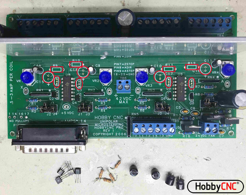
- Remove C15, C16, C17 & C18 (100uf, 16V). Red circles
Use a solder sucker or solder wick and make sure the “+” holes are clear - Remove Resistors R9, R10, R11, and R12. Red rectangles
Save one of these resistors. - Remove MOSFETS Q1, Q3, Q5 and Q7. Red ovals
Add Jumpers
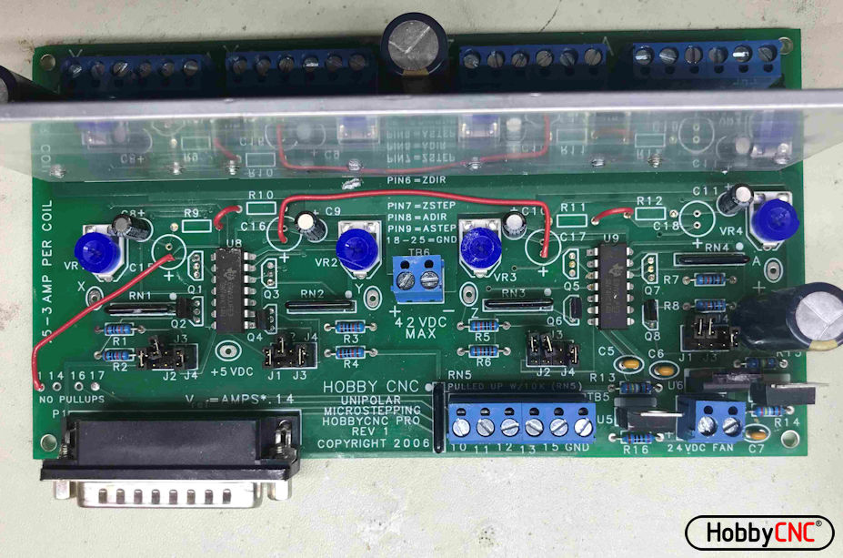
Jumper from (Red Wires)
- pin 1 of the 25pin D to the “+” of C15
- the two closest pads for R9 and R10
- the “+” of C16 to the “+” of C17
- the two closest pads for R11 and R12
Test Jumpers
Using your volt meter on the ohms range. Confirm that the pin 1 pad (next to the 25 pin D) to the drain (top) of Q1, Q3, Q5 and Q7 (pin closest to the driver ICs) to confirm continuity.
Add Jumper and pull-up resistor
Jumper (Yellow Wire and resistor)
- Solder and shrink-tube a jumper to one end of the resistor you saved
- Solder the resistor to the bottom hole where Q5 was (the hole closest to the letters “Q5” (this is + 5VDC)
- Solder the end of the wire to the “+” of C 11.
Cut 4 Traces
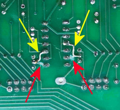
Turn the board over. Cut four traces – two at U8 and two at U9. Locations of the traces to cut are the same on U8 and U9.
Cut the traces from the gates of Q 2, Q4, Q6 and Q8 to U8 and U9 (4 places, red arrows).
Test with your ohm meter to confirm the trace is cut.
Add jumpers
Add jumpers as shown from the Gates of Q2,4,6 &8 to new pins on U8 and U9. Yellow arrows.
Power-up and test
Power-up the board and measure the voltage at the each test point.
Connect Pin 1 to ground and the voltages at the test point should drop roughly in half.


